Home
› Full Subtractor Logic Diagram And Truth : Solved Q1 A Design Full Subtractor Circuit With Two Half Chegg Com - There are two types of subtractors.
Full Subtractor Logic Diagram And Truth : Solved Q1 A Design Full Subtractor Circuit With Two Half Chegg Com - There are two types of subtractors.
Full Subtractor Logic Diagram And Truth : Solved Q1 A Design Full Subtractor Circuit With Two Half Chegg Com - There are two types of subtractors.. Full adder using truth table. So, it's very easy to realize any boolean expression by taking it's required output as minterm and oring with extra or gate. An important point worth mentioning is that the half subtractor diagram aside implements. The logic diagram of full subtractor is shown below. Ternary full subtractor, comparator, multiplier, multiplexer/demultiplexer.
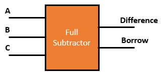
The logic symbol and truth table. Hence it has three inputs and two outputs. The two outputs d and bout represent the difference and fig.1 denotes the basic logic diagram of nft gate output borrows respectively. The truth table is a key tool to understand the working of any digital circuit. An important point worth mentioning is that the half subtractor diagram aside implements.
Full Subtractor Definition Circuit Diagram Truth Table Gate Vidyalay from www.gatevidyalay.com There are two types of subtractors. Let's assume decoder functioning by using the following logic diagram. Can some one answer this please. The truth table of this subtractor consists of the values of minuend (a), subtrahend (b) and the borrow. Cascading of full subtractor circuit. This article is contributed by harshita pandey. Full subtractor design with simple gates(1). Hence it has three inputs and two outputs.
We will write the truth table for.
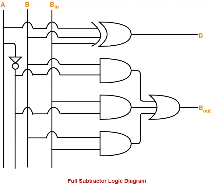
The fs works by combining the operations of basic logic gates, with the simplest form using one xor, one or, one not & three and gate. It will continue up to msb. If you like geeksforgeeks and would like to contribute, you. Adders & subtractors are wildly used in in computer's alu (arithmetic logic unit) to compute addition as well as cpu (central processing unit) and gpu (graphics processing unit) for graphics applications to reduce the circuit. So, it's very easy to realize any boolean expression by taking it's required output as minterm and oring with extra or gate. Based on the truth table. Hence it has three inputs and two outputs. Full subtractor is a combinational logic circuit used for the purpose of subtracting two single bit numbers with a borrow. A is the 'minuend', b is 'subtrahend', c is the 'borrow' produced by the previous stage, d is the difference output and c' is the block diagram. Full subtractor design with simple gates(1). The full subtractor is a combinational circuit with three inputs a,b,c and two output d and c'. The logic diagram of full subtractor is shown below. Full subtractor definition, block diagram, truth table, circuit diagram, logic diagram, boolean expression and equation are discussed.
It has two inputs, x (minuend) and y (subtrahend) and two outputs d (difference) and b (borrow). Makes no sense at all. So, it's very easy to realize any boolean expression by taking it's required output as minterm and oring with extra or gate. The block diagram and truth table of full subtractor are as below. In the above image, instead of block diagram, actual symbols are shown.
Full Subtractor Truth Table Logic Diagram Electricalvoice from electricalvoice.com The logic diagram of full subtractor is shown below. The full subtractor is a combinational circuit with three inputs a,b,c and two output d and c'. Full subtractor design with simple gates(1). Instead binary numbers are always multibits. Full subtractor using half subtractors and logic gates. The fs works by combining the operations of basic logic gates, with the simplest form using one xor, one or, one not & three and gate. We will write the truth table for. The three inputs a, b and bin, denote the minuend, subtrahend and previous borrow respectively.
Can some one answer this please.
Fugure below shows the block diagram of the full subtractor. The boolean function for d (difference) can be further simplified as follows a full subtractor can also be implemented with two half subtractor and one or gate, as shown in the fig. And full subtractor in simulator 2. Full subtractor definition, block diagram, truth table, circuit diagram, logic diagram, boolean expression and equation are discussed. The fs works by combining the operations of basic logic gates, with the simplest form using one xor, one or, one not & three and gate. The two outputs d and bout represent the difference and fig.1 denotes the basic logic diagram of nft gate output borrows respectively. Hence it has three inputs and two outputs. Hence, full substractor is similar to half. Previously, we have discussed an overview of this like construction, circuit diagram with logic gates. The full subtractor is a combinational circuit which is used to perform subtraction of three input bits: Full adder using truth table. Lecture on full subtractor explaining basic concept, truth table and circuit diagram. The logic diagram of full subtractor is shown below.
Schematic diagrams of full adders. Full subtractor definition, block diagram, truth table, circuit diagram, logic diagram, boolean expression and equation are discussed. The block diagram and truth table of full subtractor are as below. It will continue up to msb. The truth table is a key tool to understand the working of any digital circuit.
Design A Full Subtractor Using 4 To 1 Mux And An Inverter Electrical Engineering Stack Exchange from i.stack.imgur.com An important point worth mentioning is that the half subtractor diagram aside implements. We will write the truth table for. The combinational logic circuit performs this operation is called full substractor. Hence it has three inputs and two outputs. Fugure below shows the block diagram of the full subtractor. Full subtractor definition, block diagram, truth table, circuit diagram, logic diagram, boolean expression and equation are discussed. Cascading of full subtractor circuit. If you like geeksforgeeks and would like to contribute, you.
The full subtractor is a combinational circuit with three inputs a,b,c and two output d and c'.
It has two inputs, x (minuend) and y (subtrahend) and two outputs d (difference) and b (borrow). The three inputs a, b and bin, denote the minuend, subtrahend and previous borrow respectively. Full subtractor is a combinational logic circuit used for the purpose of subtracting two single bit numbers with a borrow. Full subtractor a combinational circuit with truth table and logic diagram. Fugure below shows the block diagram of the full subtractor. If you like geeksforgeeks and would like to contribute, you. The half subtractors designed can be used in the the subtractor designed by logic gates is described below. In the above image, instead of block diagram, actual symbols are shown. Instead binary numbers are always multibits. The two outputs d and bout represent the difference and fig.1 denotes the basic logic diagram of nft gate output borrows respectively. Logical expression for difference, logical expression for borrow, fig.3 logic diagram for fs. Theory subtractor circuits take two binary numbers as input and subtract one binary number input from the other subtraction of two bits. Subtractor circuits take two binary numbers as input and subtract one binary number input from the other binary number input.