Home
› Lm2596S Circuit Diagram - potentiometer - How to adjust the voltage of this SMPS? - Electrical Engineering Stack Exchange / Nsc, alldatasheet, datasheet, datasheet search site for electronic components and semiconductors, integrated circuits, diodes, triacs.
Lm2596S Circuit Diagram - potentiometer - How to adjust the voltage of this SMPS? - Electrical Engineering Stack Exchange / Nsc, alldatasheet, datasheet, datasheet search site for electronic components and semiconductors, integrated circuits, diodes, triacs.
Lm2596S Circuit Diagram - potentiometer - How to adjust the voltage of this SMPS? - Electrical Engineering Stack Exchange / Nsc, alldatasheet, datasheet, datasheet search site for electronic components and semiconductors, integrated circuits, diodes, triacs.. Nsc, alldatasheet, datasheet, datasheet search site for electronic components and semiconductors, integrated circuits, diodes, triacs. We have collected these discussions here and presenting it to you. The complete circuit diagram is given below, you can often find. Block diagram and typical application. The lm2596 series of regulators are monolithic integrated.
The lm2596 series of regulators are monolithic integrated. The lm2596 regulator is monolithic integrated circuit ideally suited for easy and convenient design of a step−down switching regulator (buck converter). This device is available in adjustable output version and it is internally. It is capable of driving a 3.0 a load with excellent line and load regulation. Block diagram and typical application maximum ratings rating maximum supply.
Lm2596 Circuit Diagram - PCB Designs from lh5.googleusercontent.com This device is available in adjustable output version and it is internally. It is capable of driving a 3.0 a load with excellent line and load regulation. Lm2596 based dc buck convertor | circuit diagram and pinout. Nsc, alldatasheet, datasheet, datasheet search site for electronic components and semiconductors, integrated circuits, diodes, triacs. The adjustable version can take in input voltage from 4.5v to 40v and convert it to variable finally the output voltage is obtained through pin 2 through an lc filter. The complete circuit diagram is given below, you can often find. Block diagram and typical application. Lm2596 based dc buck convertor | circuit diagram and pinout.
Nsc, alldatasheet, datasheet, datasheet search site for electronic components and semiconductors, integrated circuits, diodes, triacs.
Block diagram and typical application. It is capable of driving a 3.0 a load with excellent line and load regulation. Lm2596 based dc buck convertor | circuit diagram and pinout. Block diagram and typical application maximum ratings rating maximum supply. I senses the regulated output voltage to complete. We have collected these discussions here and presenting it to you. Nsc, alldatasheet, datasheet, datasheet search site for electronic components and semiconductors, integrated circuits, diodes, triacs. Nice to meet you, now you are in the wiring diagram circuitdiagramimages.blogspot.com website, you are opening the page that contains the picture wire wiring diagrams or schematics about lm2596 circuit diagram. The lm2596 regulator is monolithic integrated circuit ideally suited for easy and convenient design of a step−down switching regulator (buck converter). The lm2596 series of regulators are monolithic integrated. Vero board jumper wires circuit diagram: The adjustable version can take in input voltage from 4.5v to 40v and convert it to variable finally the output voltage is obtained through pin 2 through an lc filter. The complete circuit diagram is given below, you can often find.
Block diagram and typical application. Lm2596 based dc buck convertor | circuit diagram and pinout. I senses the regulated output voltage to complete. The lm2596 series of regulators are monolithic integrated. It is capable of driving a 3.0 a load with excellent line and load regulation.
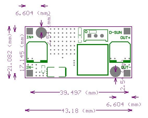
LM2596 Module , Adjustable DC/DC Power Converter (1.25V - 35V/3A) - EasyEDA from easyeda.com Lm2596 based dc buck convertor | circuit diagram and pinout. Block diagram and typical application. Nice to meet you, now you are in the wiring diagram circuitdiagramimages.blogspot.com website, you are opening the page that contains the picture wire wiring diagrams or schematics about lm2596 circuit diagram. Block diagram and typical application maximum ratings rating maximum supply. The lm2596 regulator is monolithic integrated circuit ideally suited for easy and convenient design of a step−down switching regulator (buck converter). I senses the regulated output voltage to complete. Lm2596 based dc buck convertor | circuit diagram and pinout. The complete circuit diagram is given below, you can often find.
Vero board jumper wires circuit diagram:
Nice to meet you, now you are in the wiring diagram circuitdiagramimages.blogspot.com website, you are opening the page that contains the picture wire wiring diagrams or schematics about lm2596 circuit diagram. Lm2596 based dc buck convertor | circuit diagram and pinout. The lm2596 regulator is monolithic integrated circuit ideally suited for easy and convenient design of a step−down switching regulator (buck converter). The lm2596 series of regulators are monolithic integrated. I senses the regulated output voltage to complete. Block diagram and typical application maximum ratings rating maximum supply. The complete circuit diagram is given below, you can often find. It is capable of driving a 3.0 a load with excellent line and load regulation. Lm2596 based dc buck convertor | circuit diagram and pinout. The adjustable version can take in input voltage from 4.5v to 40v and convert it to variable finally the output voltage is obtained through pin 2 through an lc filter. Block diagram and typical application. Vero board jumper wires circuit diagram: Nsc, alldatasheet, datasheet, datasheet search site for electronic components and semiconductors, integrated circuits, diodes, triacs.
It is capable of driving a 3.0 a load with excellent line and load regulation. The adjustable version can take in input voltage from 4.5v to 40v and convert it to variable finally the output voltage is obtained through pin 2 through an lc filter. The complete circuit diagram is given below, you can often find. We have collected these discussions here and presenting it to you. I senses the regulated output voltage to complete.
Lm2596 Module Circuit Diagram - Circuit Boards from ph-live-01.slatic.net It is capable of driving a 3.0 a load with excellent line and load regulation. The lm2596 regulator is monolithic integrated circuit ideally suited for easy and convenient design of a step−down switching regulator (buck converter). Lm2596 based dc buck convertor | circuit diagram and pinout. The lm2596 series of regulators are monolithic integrated. Nsc, alldatasheet, datasheet, datasheet search site for electronic components and semiconductors, integrated circuits, diodes, triacs. The complete circuit diagram is given below, you can often find. Vero board jumper wires circuit diagram: I senses the regulated output voltage to complete.
The lm2596 series of regulators are monolithic integrated.
The complete circuit diagram is given below, you can often find. The lm2596 series of regulators are monolithic integrated. Vero board jumper wires circuit diagram: I senses the regulated output voltage to complete. We have collected these discussions here and presenting it to you. Nsc, alldatasheet, datasheet, datasheet search site for electronic components and semiconductors, integrated circuits, diodes, triacs. It is capable of driving a 3.0 a load with excellent line and load regulation. Lm2596 based dc buck convertor | circuit diagram and pinout. Nice to meet you, now you are in the wiring diagram circuitdiagramimages.blogspot.com website, you are opening the page that contains the picture wire wiring diagrams or schematics about lm2596 circuit diagram. The lm2596 regulator is monolithic integrated circuit ideally suited for easy and convenient design of a step−down switching regulator (buck converter). Block diagram and typical application. The adjustable version can take in input voltage from 4.5v to 40v and convert it to variable finally the output voltage is obtained through pin 2 through an lc filter. Block diagram and typical application maximum ratings rating maximum supply.