Tube Light Connection Drawing
110801 pt typical pipe trace section. Fix the switch and tube light fitting in the marked positions.

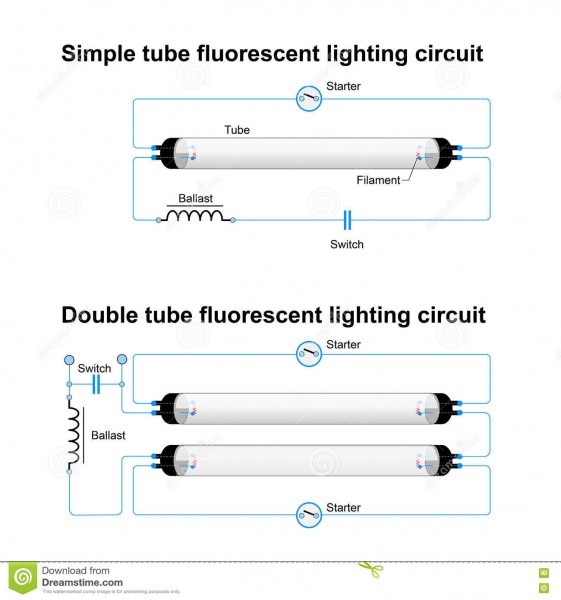
Wiring Diagram of Twin Tube Light Electrical Revolution
In an led thermal runaway situation the led starts drawing more current, and begins getting warmer due to the absence of a current control limit.

Tube light connection drawing. When you are trying to replace fluorescent lighting, whether, with leds or another tube, you will need to understand the difference between tube light sizes. 2) the configuration of the leds on the led strip. All you need is a powerful software.
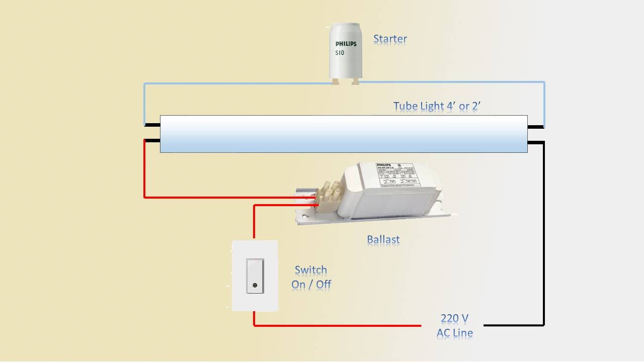
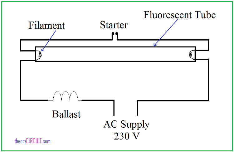
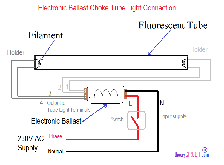
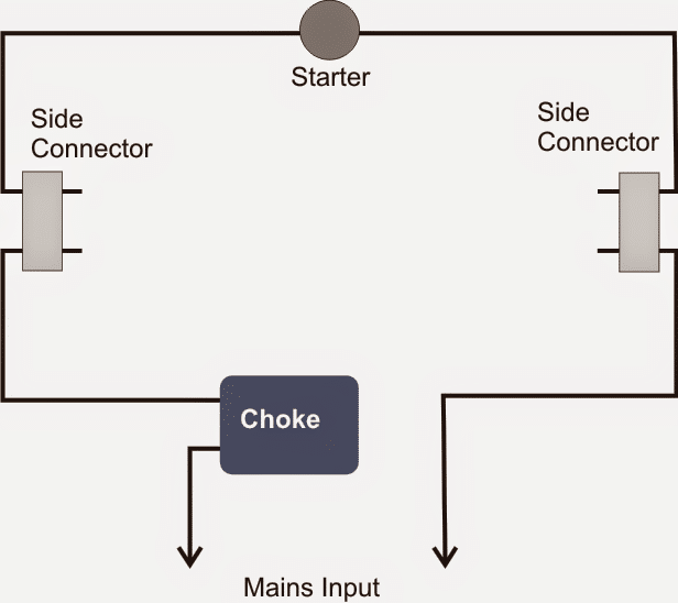
Very simple :) main parts of tube light are 1. Electronic choke has one input and two output. Fluorescent tubes/lamps are filled with mercury vapor.
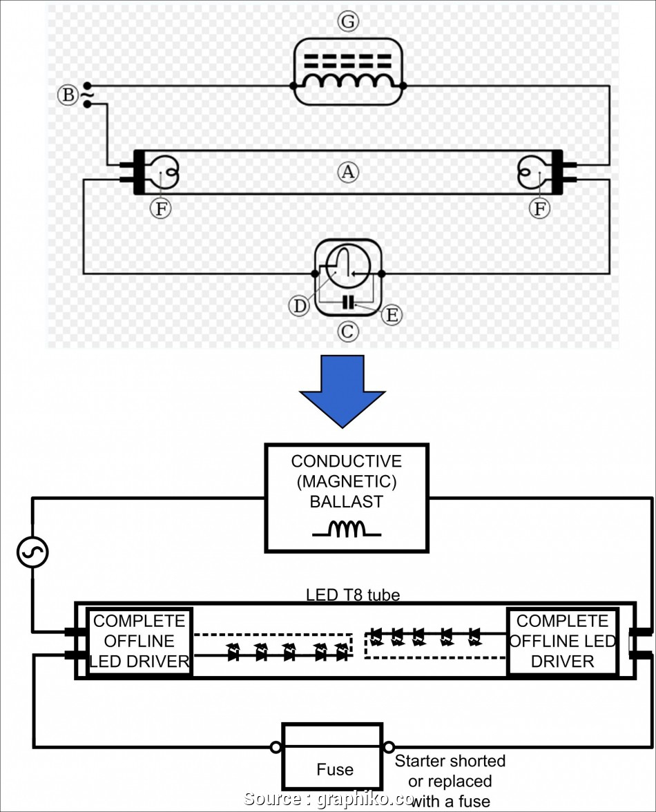
The vector stencils library lighting is included in the electric and telecom. Test the working of the tube light by giving electric supply to the 2) remove or short ballast and starter if present.
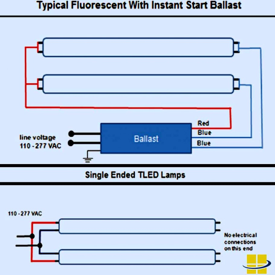
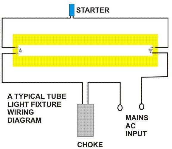
No power will be run to the other end (the diagram below is for single end led t8 ballast bypass lamps). Here is one example of a tube light fixture consisting of a large heavy square "choke" or "ballast" and a small cylindrical "starter." let's try to understand how the whole system works. The choke is in fact a large.
Only one pin is hot wire, the remaining pins are cold wire Peel apart the wires an inch back. 110603 pt typical double trace.
In standard fluorescent tubes, smaller diameters almost always mean better efficiency. This solution provides 26 libraries which contain 926. 1) the specified voltage of the leds and components used, and.
Lighting circuits connections for interior electrical installations. Mark the switch and tube light location points and draw lines for wiring on the wooden board. 4) see diagram below for proper wiring information.
Use these shapes for drawing lighting design floor plans, circuit schematic and wiring diagrams, cabling layouts, and reflected ceiling plans in the conceptdraw pro diagramming and vector drawing software. As you see in the above diagram the input of the electronic choke is connected to the switch board for power supply. Fluorescent lights are among the most popular lighting system used worldwide.
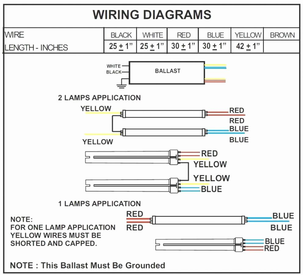
Here is no need of tube light starter. Because typical cad details are provided in autocad format, you will need a cad viewer to see autocad details. T8 led wiring instruction diagram (with ballast & starter) 1) remove original t8 fluorescent tube.
Fluorescent tube lighting comes in a range of sizes. This diagram illustrates wiring for one switch to control 2 or more lights. Download the free autodesk® dwg trueview™ by clicking the download icon.
From each main distribution panel at least two lighting supply lines are leaving, so a failure on one line does not sink the entire installation in the dark. The connection diagram of tube light with electronic choke is very simple. The phase conductor must be brown or.
This is shown in the following image which features the led tube light connection diagram. The reason is that the two pins on each end of the led tube light expect the same polarity, so whether or. Insulation on the conductors must show the colors required by the regulations.
I need some help with set this up with a red dimmer. 110603 pt typical pipe trace. Place wires along the lines and fix them with the help of clips.
I have a knob and tube setup like this the neutral line does not go to any of the switches and returns directly to the box and the hot line comes straight from the box: Repeat the process for the following colors: This is the simplest arrangement.
It wasn't so easy to create electrical symbols and electrical diagram as it is now with electrical diagram symbols offered by the libraries of electrical engineering solution from the industrial engineering area at the conceptdraw solution park. You can use this to calculate the diameter of different sized led tube lights. Please refer to the circuit diagram on the right as you read the following points:
How to create electrical diagram? Current control in an led tube light becomes crucial because leds are current sensitive devices and can quickly get into a thermal runaway situation, ultimately damaging it permanently. 3) insert t8 led replacement into luminaire.
Leetcat april 2, 2021, 7:06pm #1. Complete the wiring as per the wiring diagram. The hot and neutral terminals on each fixture are spliced with a pigtail to the circuit wires which then continue on to the next light.
The vector stencils library lighting contains 55 symbols of lighting devices and equipment. Determining the tube size of the fluorescent light will help you decide which tube lighting is a suitable replacement.

Double Tube Light Circuit Diagram
Convert Fluorescent To Led Wiring Diagram Cadician's Blog
Tube Light Wiring Connection Earth Bondhon

Led Fluorescent Tube Replacement Wiring Diagram Download
Convert Fluorescent To Led Wiring Diagram Cadician's Blog
tube light connection drawing Wiring Diagram and Schematics

tube light circuit diagram How to make Fluorescent Tube

Led Fluorescent Tube Replacement Wiring Diagram Download
tube light connection drawing Wiring Diagram and Schematics

T5 Led Tube Wiring Diagram bookingritzcarlton.info

Trailer Led Light Wiring Diagram Trailer Wiring Diagram

T8 Led Wiring Diagram Sample Wiring Collection
Twin Fluorescent Lamp Wiring Diagram
How To Read A Ballast Wiring Diagram Cadician's Blog
How Do Fluorescent Tube Lights Work? Explanation & Diagram
T8 Led Tube Wiring Diagram, http//bookingritzcarlton.info

tube light connection drawing Wiring Diagram and Schematics

Osram Led Tube Wiring Diagram
Compatible LED Tube Light Circuit for Standard Ballast